


/// Project : Glasbaum
Date: 1998
Location: Aachen, Testing area for Faculty of Architecture
Project manager: Dorothee S1pp
Team members: V Decren. S. Deffur, M. Fleckenstein, Ch. Gatzen, K. /ieten, C. Volberg
Technical support: Institute for steel construction| RWTH Aachen
Sponsored by: Schott Rohrglas
Concept:Glass tubes have perfectly corresponding act towards loads, based on their cross section.
This project, which is consists of a branching tree structure of glass tubes, however it goes far beyond the simple use of tubular supports.
Another materials had been already tested to form the same structure, which led to that glass tree is the optimal solution (Fig 01. Tree support) .
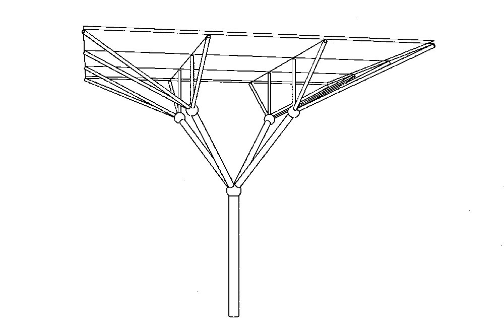
Supporting Structure: After analyzing the possible ways and geometries, it was realized that the glass tree, which was formed out of two levels of connections, only needs to carry small horizontal loads that way.
The geometry of the tree corresponds perfectly towards the distribution of the forces, the weight of the roof initiated as pressure loads in the glass branches, which transferred to the foundation, as the foundation is consist of concrete ring (Fig 02,03, Glass tree support, section upper connection) .
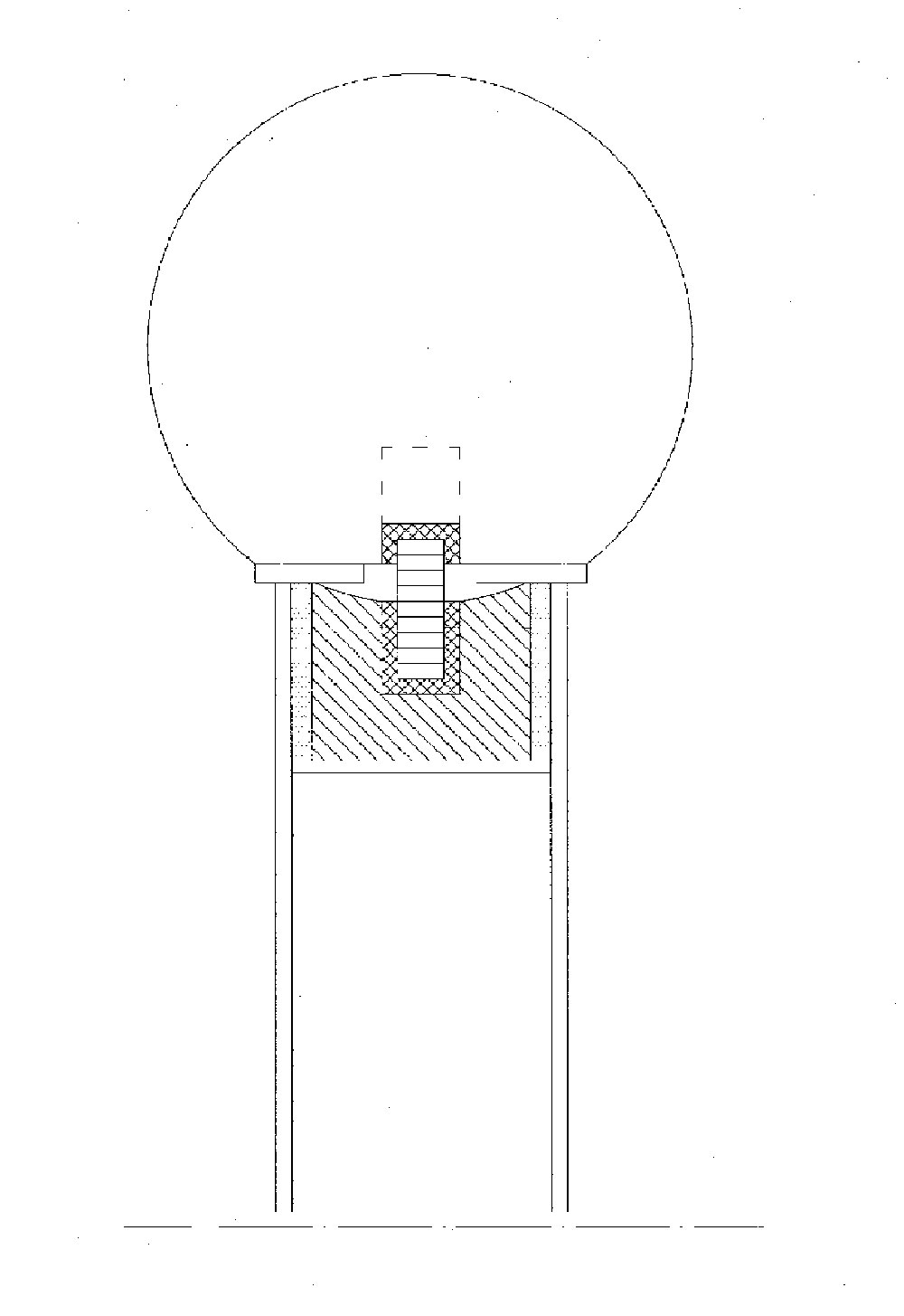
Construction: The connection between the glass tubes were proposed to use cast steel elements or CNC nodes, but for cost reasons, simple plastic balls made of epoxy resin with embedded bolts had been used. The connections were sealed with silicone. PVC sleeves had been used as a buffer between the glass tubes and the plastic connection, the bottom connection had also been sealed and fixed with bolts.
The first attempt to mount the glass tree had been failed, due to the failure of the central VSG support. The corresponding detail had been changed by flatten the contact area with the glass tube to prevent horizontal forces to be effecting the glass tubes (Fig 04,05,06. Isometric detail, Connecting detail, Connecting detail) .
Glass: The main glass tube had made of laminated safety glass with 12.50 cm diameter and thickness of 1.25 cm. all other branches were made of heat strengthen glass. the four secondary arms had a diameter of 7.50 cm and thickness of 4.20 mm, the rest branches had a diameter of 3.80 cm and 2.80 mm thickness (Fig. 07,Overview for tree support).
Comments: When executing tree support a necessary safety factors had to be granted, in the second attempt, according to geometry inaccuracies, glass crack in the main branch occurred, a long term lifting capacity cannot be guaranteed, using laminated safety glass in all levels can reduce collapsing risk. Nevertheless further investigations for the stability of the laminated glass tubes are needed.
