


/// Project : Entrance facade for Natural and Engineering sciences Building, FH Aachen / Dept. Jülich
Date: 1999
Location: Jülich – Solarcampus
Project manager: U. Knaack, W. Führer
Team members: J. Hermann
Owner: Staatliches Bauamt, Düren
Execution : Felder Stahl- und Metallbau GmbH
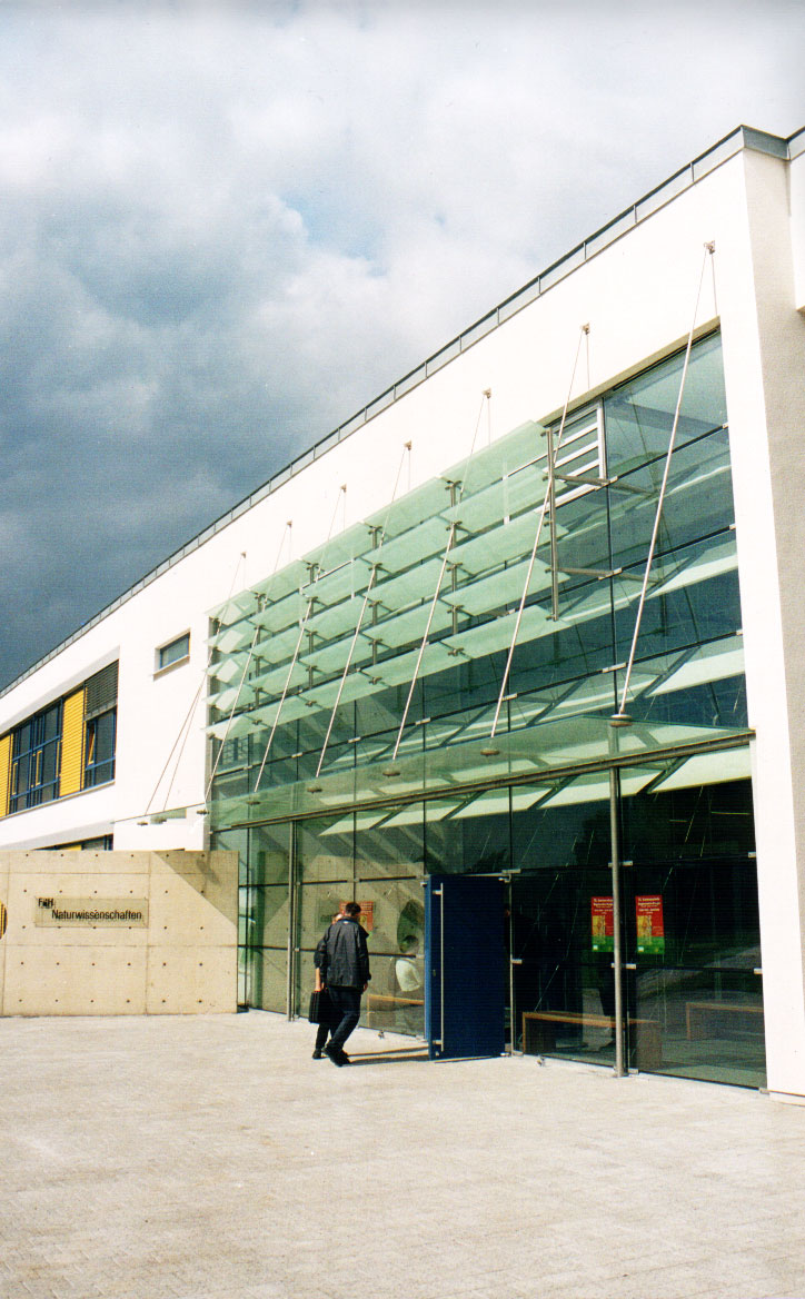
Concept: For Natural and engineering sciences Aachen University of Applied Sciences| Department Jülich building’s entrance a double skin facade had been proposed for controlling the entire building climate conditions.
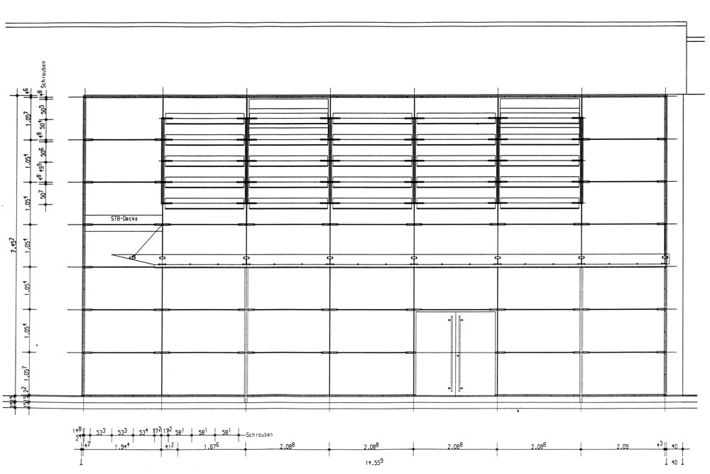
The concept was to have an outer insulating glass layer and inner single glass layer with ventilation slots on both sides to allow air flow control in summer and winter, an additional shading louvers were added to avoid over heating during summer period (Fig 01,02,03, Exterior view,Interior view, System section) .
Supporting Structure: The facade structure consists of two 7 m high glass lattice, both sides connected respectively by rods to round connection, the wind loads transferred through the outer layer towards the inner layer.
The system has 2 m module compose 20 m aver all length, the outer layer has an additional weight from the shading louvers and the canopy.
Rotating connections were provided for the louvers and the door connections to hold the system loads, in case of panel failure the adjacent connection adjust the loads. Testing shows that the system can support higher loads for glass elements, which shows that in case of failure of bigger parts the system still is safe (Fig 04, Layout ) .
Construction: Each panel placed on the top of the other and connected by clamping profiles to prevent them from sliding, also the rods of the truss system are fixed on the same points. Dead loads and horizontal loads transferred to the bottom connection which is consist of flat steel plates located at the base.
The top fixing point connected via apertures in order to prevent vertical loads transmission, only the horizontal loads from the wind were taken into account.
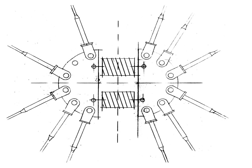
Spider connection placed between the trusses connected by the rods to hold the horizontal forces (Fig 05. Horizontal section detail for the outer facade: clamping connection with V shape with the connected rod) .
Glass: The outer layer is insulated glass unit consist of 12 mm laminated safety glass with internal 6 mm heat strengthened glass.
The inner layer consist of 10 mm ESG placed in between two 6 mm TVG panels.
The canopy dimensions is 2 * 2 m consist of 2 * 12 mm TVG panels, the shading louvers consisted of 2 * 10 mm TVG panels (Fig. 06, center spider connection).
