


/// Project : Glas-Stahl-Tragwerk
Date: 1996
Location: Aachen, Testing area for Faculty of Architecture
Project manager: Wilfried Führer, Ulrich Knaack, Mario Runkel, Valerie Spalding, Yves Weinand
Team members: I. Giemens, P. Gaube, T. Gövert, C. Hönigschmid, A. lpekci, R. Schiffers, B. Wanzek
Sponsored by: Felder I Pfeiffer I VEGLA I Weller u.a.
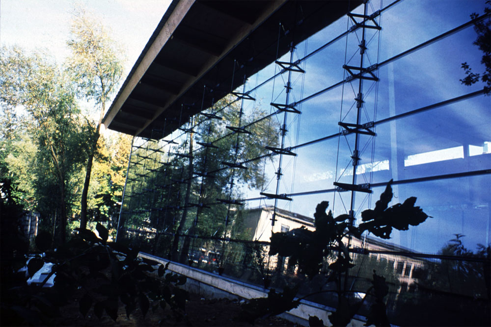
Concept: Concerning the north facade of the faculty of architecture library a glass steel structure was designed.
The glass was considered as a separation partition and a part of the supporting structure.
It was important for the design that the system should be self contained.
It should be manufactured of simple, semi finished elements (Fig 01 North facade for the library) .
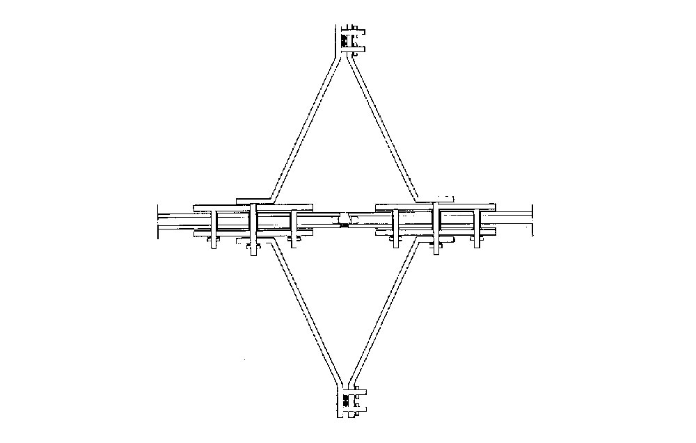
Supporting Structure: The realized system is similar to the human spine, from lattice truss and the compression chord placed in the middle, the steel parts are penetrating the glass surface for the rigidity of the system.
the 6 * 20 m facade is consist of ten fields with nine vertical lattice truss, facade glass is fixed from both sides with compression chords and pre stressed tie rods.
the cables are holding the seven glass panels and also the weight of the construction, the system is closed to itself carrying no loads from the building (Fig 02,03,04,05. vertical section, horizontal section, facade section, facade section) .
Construction: In detailing process, it was taken in to account to use simple methods by no need to drill the glass panels in a way to apply low cost production process.
Compression bars, clamps and edge connections were produced from 10 mm flat rolled galvanized steel, the connections were fixed with screws through the joints between the glass panels, the vertical joints were fixed with slotted nodes with the diagonal rods.
The arrangement of the lattice was literally tilted to prevent any intersection between the rods.
The bottom connection was consist of U shape beams and steel profiles connected with the diagonal rods (Fig 06. Isometric detail) .
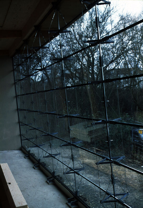
Glass: The glass panels were considered as the compression elements in the truss lattice, the 2*0.80 m insulating glass panels were consist of two 6 mm ESG panels with 14 mm air gap, they were arranged across their short span.
In case of glass unit failure, the connecting connections equivalent the loads, this loading case was for the significance of the design (Fig. 07,08,09,10 facade detail, inner view, facade detail, exterior view).
Comments: Despite using glass as main structure element, this was simple to achieve. this was achieved only through the loads of the panels, for that movements details were required.
The system is applicable in case of horizontal and free forms use.
